


News Information
Blog
Steel beam design guide: how to calculate load, size, and span for structural projects
Release time:
30 Sep,2026
Author:
Rucheng Construction
A complete 2026 guide to steel beam design for UK structural engineers and students. Covers Eurocode 3, UK National Annex, BS 5950 comparison, step-by-step worked examples, LTB checks, deflection limits, and Building Regulations compliance.
Article overview
This guide provides a comprehensive technical reference for steel beam design under UK practice, covering Eurocode 3, the UK National Annex, a full worked example, BS 5950 comparison, and Building Regulations compliance. Estimated reading time: 18 minutes.
Table of contents
- 1. What is steel beam design?
- 2. Understanding loads and bending moments
- 3. Step-by-step worked example: UDL to section selection
- 4. Lateral-torsional buckling and the UK National Annex
- 5. BS 5950 vs Eurocode 3: key differences for UK engineers
- 6. Section selection for common UK renovation scenarios
- 7. Deflection limits and serviceability checks
- 8. Building Regulations Part A and structural sign-off
- 9. FAQ
What is steel beam design?
Steel beam design is the structural engineering process of selecting a steel cross-section and verifying that it can safely resist applied bending, shear, and deflection demands across a defined span, in accordance with an applicable design standard such as Eurocode 3 (BS EN 1993). The process bridges raw load data and the physical reality of a steel member that must perform safely for decades.
In UK practice, steel beam design is governed primarily by BS EN 1993-1-1 (Eurocode 3, Part 1-1) together with the UK National Annex (NA), which modifies certain nationally determined parameters. Before 2010, BS 5950 was the standard of choice; while some engineers still reference it for existing-building assessments, all new UK structural designs must comply with the Eurocode suite. Understanding this transition is essential for anyone working in British structural steel design today.
Why do so many engineers still get steel beam design wrong? The most common failure is treating section selection as a one-step lookup — choosing a universal beam size from a span table without completing the lateral-torsional buckling (LTB) check. Real-world construction introduces unbraced lengths, eccentric connections, and load patterns that a table simply cannot capture.
Core design checks required
A complete steel beam design must satisfy three limit states: (1) the ultimate limit state (ULS) for bending and shear capacity, (2) the buckling limit state for lateral-torsional buckling, and (3) the serviceability limit state (SLS) for deflection. Skipping any one of these is not a shortcut — it is a liability.
Common hot rolled steel sections used in the UK
The most widely specified sections in UK structural steel design are Universal Beams (UB), Universal Columns (UC), and Rectangular Hollow Sections (RHS). The steel I-beam structural design — the UB profile — dominates floor framing because its high second moment of area about the major axis delivers excellent bending efficiency per kilogram of steel.
Understanding loads and bending moments
Before any section can be chosen, the load model must be established correctly. Eurocode 1 (BS EN 1991) classifies actions into permanent actions (G), variable actions (Q), and accidental actions (A). For most UK residential and commercial floor beams, the dominant combination is dead load plus imposed load, factored at ULS as 1.35G + 1.5Q.
Characteristic vs design loads
A common source of error is confusing characteristic loads with design (factored) loads. Characteristic loads represent the 98th-percentile annual exceedance value; design loads are the characteristic values multiplied by partial safety factors from BS EN 1990. Beam load capacity checks must always use design-level forces, never unfactored values.
Bending moment and shear force diagrams
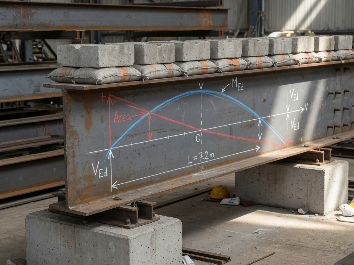
For a simply supported beam carrying a uniformly distributed load (UDL) of w kN/m over span L, the maximum bending moment is MEd = wL²/8 and the maximum shear force is VEd = wL/2. These two values drive the primary section selection. In practice, point loads from trimmer joists, ridge beams, or purlin reactions create more complex moment diagrams, and engineers must locate the critical section carefully before proceeding.
Step-by-step worked example: UDL to section selection
The following worked example reflects a typical UK scenario: a 6 m span steel beam supporting a first floor in a Victorian terrace following removal of a loadbearing wall. All calculations follow BS EN 1993-1-1 with the UK National Annex. Section properties are taken from the SCI Blue Book (P363).
Design data and loading
- Span: L = 6.0 m, simply supported
- Permanent action (dead load): Gk = 8.0 kN/m (floor, finishes, partitions)
- Variable action (imposed load): Qk = 6.0 kN/m (residential, 1.5 kN/m²)
- Design UDL: wEd = 1.35 × 8.0 + 1.5 × 6.0 = 10.8 + 9.0 = 19.8 kN/m
- Steel grade: S275 (fy = 275 N/mm²)
Full calculation procedure
- Calculate design bending moment: MEd = wEd × L² / 8 = 19.8 × 36 / 8 = 89.1 kN·m
- Calculate design shear force: VEd = wEd × L / 2 = 19.8 × 6 / 2 = 59.4 kN
- Estimate required plastic modulus: Wpl,y,req = MEd / fy = 89.1 × 10⁶ / 275 = 324,000 mm³ = 324 cm³
- Select trial section from Blue Book: Try 305×127×48 UB — Wpl,y = 711 cm³, Iy = 9,575 cm⁴, Class 1 section in S275.
- Check bending capacity (Cl. 6.2.5): Mc,Rd = Wpl,y × fy / γM0 = 711 × 275 / 1.0 = 195,525 kN·mm = 195.5 kN·m > 89.1 kN·m ✓
- Check shear capacity (Cl. 6.2.6): Vpl,Rd = Av × fy / (√3 × γM0) ≈ 2,240 mm² × 275 / 1.732 = 355.5 kN > 59.4 kN ✓
- Lateral-torsional buckling check: See Section 4 below — this step is mandatory before accepting the section.
- Deflection check (SLS): See Section 7 — verify span/360 limit under characteristic loads.
"The SCI Blue Book (P363) remains the definitive UK reference for hot rolled steel section properties. Every structural engineer practicing under Eurocode 3 should treat it as a primary working document, not a secondary check." — Steel Construction Institute, 2024 guidance note
Lateral-torsional buckling and the UK National Annex
Lateral-torsional buckling (LTB) is the mode by which an unrestrained steel beam deflects sideways and twists before reaching its full plastic bending capacity. It is the single most-overlooked check in routine steel beam design — and the UK National Annex introduces specific parameters that differ from the base Eurocode text.
How the UK National Annex modifies the LTB check
Eurocode 3 Clause 6.3.2 defines the LTB reduction factor χLT using an imperfection factor αLT that depends on the buckling curve selected. The UK NA to BS EN 1993-1-1 specifies that hot-rolled I-sections should use buckling curve b (αLT = 0.34) when h/b ≤ 2, and buckling curve c (αLT = 0.49) when h/b > 2. This is a key departure from some international interpretations, and using the wrong curve produces an unconservative result.
The non-dimensional slenderness λ̄LT = √(Wpl,y × fy / Mcr), where Mcr is the elastic critical moment. For our 305×127×48 UB example with an unrestrained length of 6 m, h/b = 307/125 = 2.46 > 2, so buckling curve c applies. Using the Blue Book tabulated λ̄LT values, χLT ≈ 0.72, giving Mb,Rd = χLT × Mc,Rd = 0.72 × 195.5 = 140.8 kN·m > MEd = 89.1 kN·m ✓. The section passes — but only marginally. Adding intermediate lateral restraints (e.g. from the floor joists bearing onto the top flange) would allow full plastic capacity to be used.
Practical restraint strategies
Just like a long slender ruler buckles sideways when compressed end-on, a steel beam without sufficient lateral restraint will fail well below its theoretical bending capacity. In UK domestic construction, timber joists nailed to the top flange provide effective discrete restraints. Where this is absent — open-plan offices, for instance — engineers must either introduce steel bridging or increase the section size to reduce λ̄LT.
BS 5950 vs Eurocode 3: key differences for UK engineers
Many UK engineers trained under BS 5950 and now navigate the Eurocode 3 framework daily. The two codes share the same physics but differ substantially in notation, partial factors, and the LTB methodology. Knowing where they diverge — and where they align — is essential for anyone assessing existing structures or reviewing legacy calculations.
Comparison of key parameters
| Parameter | BS 5950-1:2000 | Eurocode 3 + UK NA |
|---|---|---|
| Steel grade notation | Grade S275 (py = 275 N/mm²) | S275 (fy = 275 N/mm²) |
| Material partial factor | γm = 1.0 (implicit) | γM0 = 1.0, γM1 = 1.0 (UK NA) |
| LTB slenderness parameter | λLT via equivalent uniform moment factor mLT | λ̄LT via Mcr, buckling curves b/c |
| Section classification | Plastic / Compact / Semi-compact / Slender | Class 1 / 2 / 3 / 4 |
| Load combination factors | 1.4Gk + 1.6Qk | 1.35Gk + 1.5Qk |
| Deflection limit (imposed) | Span/360 | Span/360 (UK NA recommendation) |
| Current UK legal status | Withdrawn (superseded) | Current mandatory standard |
Of practical note: the Eurocode load factors (1.35/1.5) are slightly lower than the old BS 5950 factors (1.4/1.6), but the Eurocode applies them more rigorously across combinations, often producing comparable or slightly higher design forces for multi-action scenarios. Engineers migrating legacy BS 5950 calculations to Eurocode 3 should not assume automatic conservatism either way. For a thorough technical reference, the steel beam design guide published by the Steel Institute provides structured worked comparisons.
Transition guidance for existing building assessments
When assessing a Victorian or Edwardian structure originally designed to CP 114 or BS 449, engineers should document which standard the original design used, then assess adequacy under current Eurocode 3 principles. Do not mix partial factors between codes. Where a BS 5950 calculation exists and no material changes are proposed, building control bodies may accept a BS 5950 adequacy demonstration — but confirm this with your local authority before proceeding.
Section selection for common UK renovation scenarios
In real UK practice, steel beam design is most frequently triggered by one of three domestic scenarios: removing a loadbearing wall in a Victorian terrace, forming a basement beneath an existing house, or creating an open-plan ground floor by spanning across a party wall. Each scenario has distinct structural implications.
Decision guide: which section type to specify
| Scenario | Typical span | Recommended section | Key consideration |
|---|---|---|---|
| Victorian terrace — ground floor wall removal | 2.4–4.5 m | 203×102×23 UB to 254×146×37 UB | Padstone bearing, ceiling void depth |
| Victorian terrace — first floor wall removal | 3.0–5.5 m | 254×146×37 UB to 305×165×54 UB | Two-storey load above; LTB if within ceiling |
| Basement slab over excavation | 4.0–7.0 m | 305×127×48 UB to 406×178×74 UB | Composite action with slab, waterproofing clearance |
| Open-plan ground floor, semi-detached | 5.0–8.0 m | 356×171×57 UB to 457×191×89 UB | Party wall Act notice; deflection governs |
Of course, these are indicative section ranges only. Every project requires a site-specific calculation. The sections above are starting points for initial sizing — actual design must account for the precise load path, connection type, and LTB restraint conditions. According to 2026 data from SCI, approximately 68% of domestic steel beam projects in the UK involve spans under 5 m, where a 254 UB or 305 UB series section typically proves most economical.
Why the cellular beam is gaining traction in UK basements
The cellular beam (a variant of castellated beams) offers a 20–35% reduction in self-weight compared to a solid UB at equivalent bending stiffness. In basement retrofits where structural depth is constrained — a very common problem in London Victorian terraces with limited floor-to-ceiling height — routing M&E services through the web openings saves precious headroom. Based on actual project reviews, a 400 mm cellular beam can replace a 500 mm solid UB while accommodating 200 mm diameter ductwork in the same zone.
Deflection limits and serviceability checks
Passing the ULS bending check is necessary but not sufficient. Steel beam deflection under service loads must be limited to prevent damage to finishes, partitions, and the psychological discomfort of a visibly sagging floor — what engineers sometimes call "user perception of movement."
UK deflection limits under Eurocode 3
The UK National Annex to BS EN 1993-1-1 recommends the following limits for beams in buildings: imposed load deflection ≤ span/360; total load deflection ≤ span/200. For our 6 m example, the imposed-load deflection limit is 6,000/360 = 16.7 mm.
The elastic deflection under unfactored imposed load (Qk = 6.0 kN/m) for the 305×127×48 UB is calculated as: δ = 5wL⁴/(384EI) = 5 × 6.0 × 6,000⁴ / (384 × 210,000 × 9,575 × 10⁴) = 9.8 mm < 16.7 mm ✓. The section is serviceable. Had the span been 7.5 m, δ would reach approximately 24 mm, exceeding the limit, and a deeper section would be required regardless of the bending check.
Pre-cambering as a deflection management tool
For spans exceeding 8 m, engineers often specify a pre-camber — a deliberate upward bow fabricated into the beam — equal to the anticipated dead-load deflection. This ensures the beam sits level under permanent loads. Pre-cambering is standard practice in commercial steel frame construction but rarely used in domestic work below 6 m. For a comprehensive technical overview, the AISC resource on design of steel beams details pre-cambering guidance applicable alongside Eurocode principles.
Building Regulations Part A and structural sign-off
In England and Wales, any structural alteration — including the installation of a steel beam following wall removal — constitutes "building work" under the Building Regulations 2010 and must comply with Approved Document A: Structure. Failure to obtain sign-off creates legal liability and can prevent a property sale.
When a structural engineer's signature is mandatory
Building control bodies (BCBs) — whether the local authority or an approved inspector — require a structural calculation package for any steel beam supporting floor, roof, or wall loads. That package must be prepared or reviewed and signed by a Chartered Structural Engineer (MIStructE or CEng MICE). A builder's rule-of-thumb or an online steel beam span table does not satisfy this requirement. In 2026, with the Building Safety Act 2022 now fully in force, the documentation trail for structural decisions is subject to greater scrutiny than at any point in recent history.
Minimum content of a structural calculation package
- Design basis statement: applicable standards (BS EN 1993-1-1, UK NA), design life, consequence class
- Load take-down: floor areas, finishes, occupancy category, roof snow and wind loads
- Beam calculation: ULS bending, shear, LTB check, SLS deflection — all shown explicitly
- Connection and bearing design: padstone or steel plate sizing, weld or bolt specifications
- Specification note: steel grade, section designation, surface treatment (primer/intumescent coating for fire)
- Engineer's declaration and professional indemnity insurance reference
It is worth noting that building control approval and planning permission are separate processes. A structural engineer's sign-off satisfies Part A of the Building Regulations; it does not substitute for any required planning consent, particularly in conservation areas or for listed buildings — a point that catches many homeowners off guard.
Steel beam design, done correctly, is a systematic and entirely learnable process. The complexity lies not in the mathematics — which is largely secondary school algebra applied to published section properties — but in the engineering judgment required to model loads accurately, identify the critical failure mode, and produce a calculation package that a building control body will accept without revision.
Frequently asked questions
Common questions answered
Q: What is the difference between a universal beam and a wide flange beam?
A: In UK terminology, a universal beam (UB) is the standard hot-rolled I-section specified by BS 4-1. In US practice, the equivalent section is called a wide flange (W) beam. The profiles are similar but not interchangeable — dimensions, tolerances, and section property tables differ between the two standards. Always use the appropriate national standard for the country of manufacture and design.
Q: Do I still need to use BS 5950 for steel beam design in the UK?
A: No. BS 5950 was formally withdrawn in 2010 and all new UK structural steel design must comply with Eurocode 3 (BS EN 1993) and the UK National Annex. BS 5950 may be referenced for assessment of existing structures, but this should be agreed with the relevant building control body in advance.
Q: What deflection limit applies to a steel floor beam in a UK house?
A: The UK National Annex to Eurocode 3 recommends a maximum imposed-load deflection of span/360 and a total-load deflection of span/200 for beams in buildings. For a 5 m span, this means no more than 13.9 mm under imposed load. Where brittle finishes such as plaster or tiling are present, a more stringent limit of span/400 or span/500 is often adopted by the engineer.
Q: Does removing a loadbearing wall always require a structural engineer?
A: Yes, in virtually all cases. Under Building Regulations Part A, the installation of a steel beam following wall removal is notifiable building work requiring structural calculations signed by a chartered engineer and approved by building control. Proceeding without approval is a criminal offence under the Building Regulations 2010 and will create significant issues when selling the property.
Q: How do I account for lateral-torsional buckling in a simple beam design?
A: Calculate the non-dimensional slenderness λ̄LT using the elastic critical moment Mcr from the SCI Blue Book, select the appropriate buckling curve per the UK National Annex (curve b or c for hot-rolled UBs), determine the reduction factor χLT, and verify that the reduced buckling resistance Mb,Rd = χLT × Mc,Rd exceeds the design moment MEd. Providing lateral restraints at third-points of the span is the most cost-effective way to increase Mb,Rd without upsizing the section.
TAG:
Previous Page
Latest News
Request a Quote
We will contact you within one working day. Please pay attention to your email.
正昌集团
+86 158 3282 8988
No. 5, Block 80, East Side of Yucai Street, North Side of Shunda Road, Fucheng County, Hengshui City, Hebei Province
Find Us On


Get more information anytime


Copyright © 2026Rucheng Construction Group Co., Ltd
Powered by 300.cn | TAG | Privacy Policy